F20C cam sensor pinout?
-
PhillipM
- Posts: 177
- Joined: Tue May 13, 2014 5:30 am
- ECU Model: S80 Pro
- Distributor: DTA UK
- Firmware Version: 73
F20C cam sensor pinout?
Anyone know what the pinouts are on the 3-pin cam sensor for the later Honda F20C engines? Obviously I have the pinout for the 2-pin one in the DTA manual, but it got changed on the later engines and I'm struggling to find anything (sensor has no markings or part numbers on it)
Re: F20C cam sensor pinout?
Have you asked Sandy? he might know, he's meddled with a few Hondas in the past.
had a look on autodata but its rather sparse on info for these
had a look on autodata but its rather sparse on info for these
-
PhillipM
- Posts: 177
- Joined: Tue May 13, 2014 5:30 am
- ECU Model: S80 Pro
- Distributor: DTA UK
- Firmware Version: 73
Re: F20C cam sensor pinout?
Yeah, I found the same whilst looking, even the only dealer circuit diagram I can find is for the 2-pin one.
-
Roverdose
- Posts: 318
- Joined: Tue Aug 09, 2011 2:54 pm
- ECU Model: S80 Pro
- Distributor: Roverdose
- Location: Stevenage
- Contact:
Re: F20C cam sensor pinout?
you got the engine loom there? surely a pinout will get you 2 of the in/outs?
i cant see them wiring a completely separate 3 wire's through the loom for a cam sensor.
Drew
i cant see them wiring a completely separate 3 wire's through the loom for a cam sensor.
Drew
-
stevieturbo
- Posts: 3588
- Joined: Tue Aug 02, 2011 12:08 pm
- ECU Model: No ECU
- Location: Norn Iron
Re: F20C cam sensor pinout?
If 3 pin...more than likely it's a hall sensor, so just test it.
Buy some cheapy test leads http://www.ebay.co.uk/itm/10-X-Croc-Cli ... 20b825b1fc
Very handy to have.
Get a 9v battery and a multimeter.
Often the centre pin is the signal, with the other two being power and ground. But it would be rare to do any damage by wrong connection.
Move a ferrous metal object in front of the sensor to test and you should see the voltage switch hi/lo as you do this if wiring is correct.
There are only 3 pins, so really only a small number of permutations before it's right.
If it's a 2 wire and the 3rd is a shield for the wiring, it'll be a VR sensor, and really you need a scope to test it properly.
-
PhillipM
- Posts: 177
- Joined: Tue May 13, 2014 5:30 am
- ECU Model: S80 Pro
- Distributor: DTA UK
- Firmware Version: 73
Re: F20C cam sensor pinout?
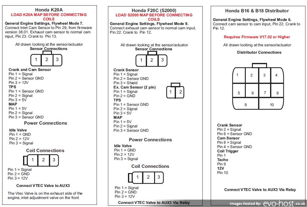
The only thing I'm worried about really, is that the K20 3 pin cam sensor takes a 12v power feed, and the F20C 2-pin takes a 5v feed. I really don't want to bugger that up...
-
stevieturbo
- Posts: 3588
- Joined: Tue Aug 02, 2011 12:08 pm
- ECU Model: No ECU
- Location: Norn Iron
Re: F20C cam sensor pinout?
If it's a hall sensor...ie 3 wire, more than likely it will be fine with 12v even if originally it used 8v or 5v.
Even 12v sensors usually work when powered with 5v. Although not always.
It would be very unusual for a 2 wire sensor to have a power supply.
Have you any wiring diagrams ?
Even 12v sensors usually work when powered with 5v. Although not always.
It would be very unusual for a 2 wire sensor to have a power supply.
Have you any wiring diagrams ?
-
PhillipM
- Posts: 177
- Joined: Tue May 13, 2014 5:30 am
- ECU Model: S80 Pro
- Distributor: DTA UK
- Firmware Version: 73
Re: F20C cam sensor pinout?
The 2 pin one is in the DTA manual, Allen has obviously done an early s2k before.
-
stevieturbo
- Posts: 3588
- Joined: Tue Aug 02, 2011 12:08 pm
- ECU Model: No ECU
- Location: Norn Iron
Re: F20C cam sensor pinout?
Nowhere on the diagram states the F20C crank or cam are powered by any voltage. Crank is clearly defined as a 2 wire + shield magnetic sensor
Likewise cam sensor is also 2 wire magnetic.
Both of these sensors do not require any power supply.
Likewise cam sensor is also 2 wire magnetic.
Both of these sensors do not require any power supply.
-
stevieturbo
- Posts: 3588
- Joined: Tue Aug 02, 2011 12:08 pm
- ECU Model: No ECU
- Location: Norn Iron
Re: F20C cam sensor pinout?
They may have added a 3rd wire...ie a shield to the later cars, or they may have changed to a hall sensor.
Again, testing as I described above with battery etc would tell you. Although again, ideally an oscilloscope would be best.
Again, testing as I described above with battery etc would tell you. Although again, ideally an oscilloscope would be best.